Most intelligent devices existing in the physical world, a quadcopter included, take input from sensors and act on them in some way, possibly producing an output.
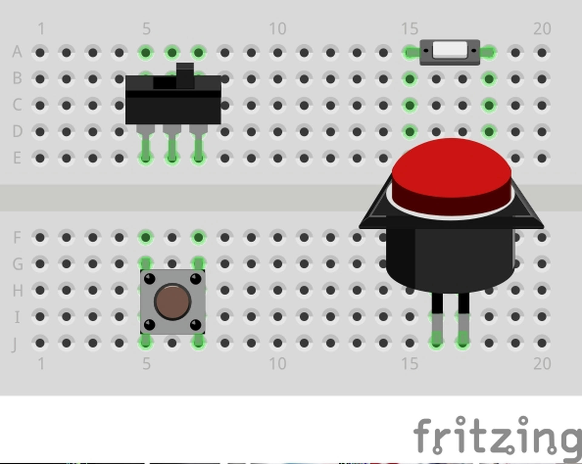
Some sensors are digital, like a button or switch, and can be read via a digitalRead() on an Arduino, returning either HIGH or LOW.
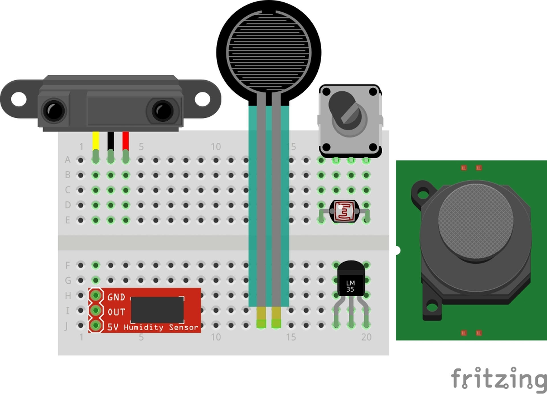
Other sensors are analog and can return anything in the range of 0-1023. These are things like potentiometers, force sensors, light sensors, and temperature sensors.
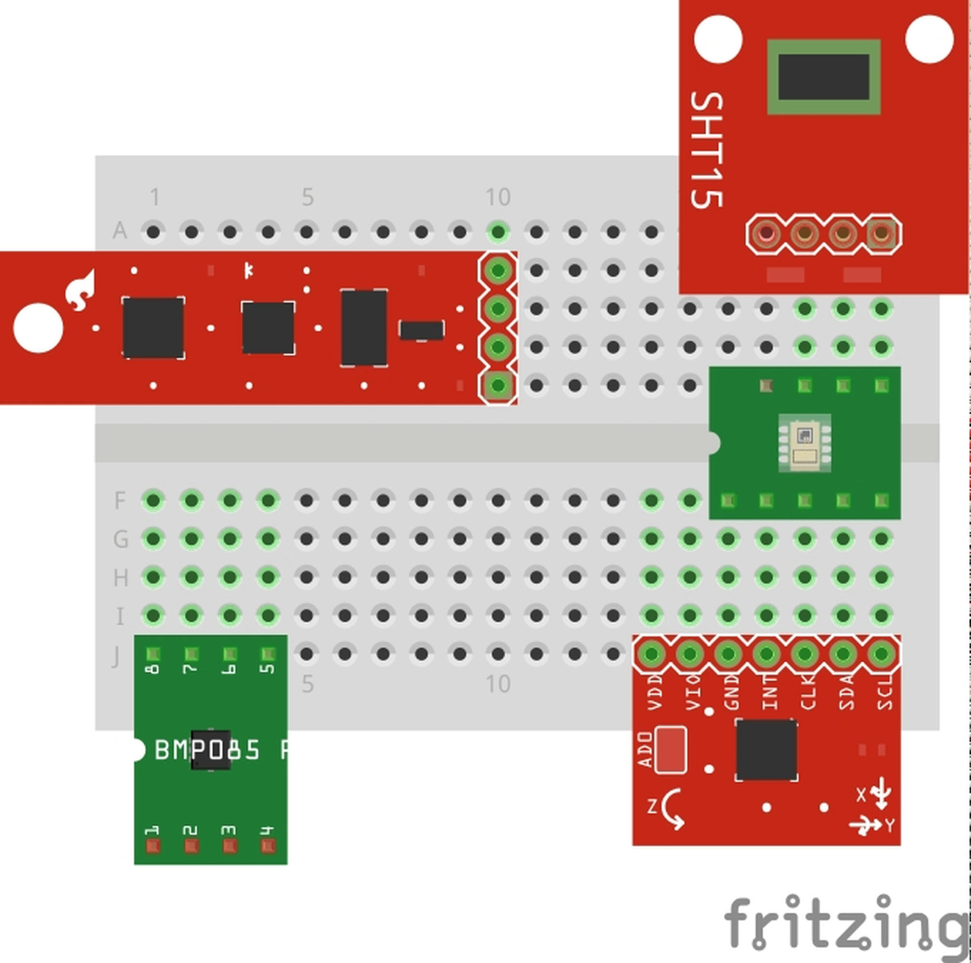
Finally, some sensors use Inter-integrated Circuit (I2C) or Serial Peripheral Interface (SPI) to interface. Typically these are found on more complicated chips like gyroscopes and accelerometers. These interfaces require multiple wires and often require you to build a small wrapper around the interface to interact with it. If you enjoy playing with Arduinos, companies like Adafruit almost always include libraries for their products.
Sensors on a Quadcopter
Despite their size, quadcopters are a outfitted with an array of sensors. If you check the board you'll see that there are only two sensor chips on the board, the MPU-925 and the LPS25H which handles pressure. The MPU-925 hosts a three-axis magnetometer, accelerometer, and gyroscope, together these offer 9 Degrees of Freedom (DOF). Combined with the pressure sensor this gives us 10DOF.
It can be a bit pricey to source integrated circuits like gyroscopes. Because of the cost we did not build Arduino labs for this part of our series, but if you'd like we'd be happy to, we just need to know!
As a note, on some of the graphs below you might notice a fair amount of noise. Some of this is inherant to the sensor, other times it is because of how we're demonstrating things. We'll talk about how to negate this at the end!
Magnetometer
Magnetometers measure the magnetic field around them, allowing the device to answer questions like which way is north? They are, essentially, a compass. The quadcopter uses this to help determine it's orientation in space.
The following video explains how one type of magnetometer, called a Fluxgate Magnometer, functions.
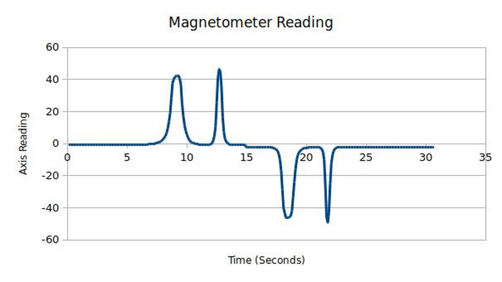
If you have one to play with you can explore it's readings by taking a reasonably strong magnet and moving it around the sensor. Notice how when we flip over the magnet we get a negative reading?
Some uses of Magnetometers:
- Aurora Detection - Magnetometers can give an indication of an aurora happening before light is visible.
- Mining - These sensors can be used to detect the composition of ground.
- Smartphones - Magnetometers play a part in how your phone tells you were you are in the world.
- Remote Sensing - There are various surveying and imagine applications including something called Magnetovision. (Cool, right?)
Gyroscope
Gyroscopes measure the rotational acceleration of the sensor. They are commonly used in planes to determine the horizon.
The gyroscope and accelerometer in a quadcopter are called a Microelectromechanical systems (MEMS). There are other, non-MEMS gyroscopes that are used widely as well that have some interesting behaivors.
A quick, basic video of how these work is below:
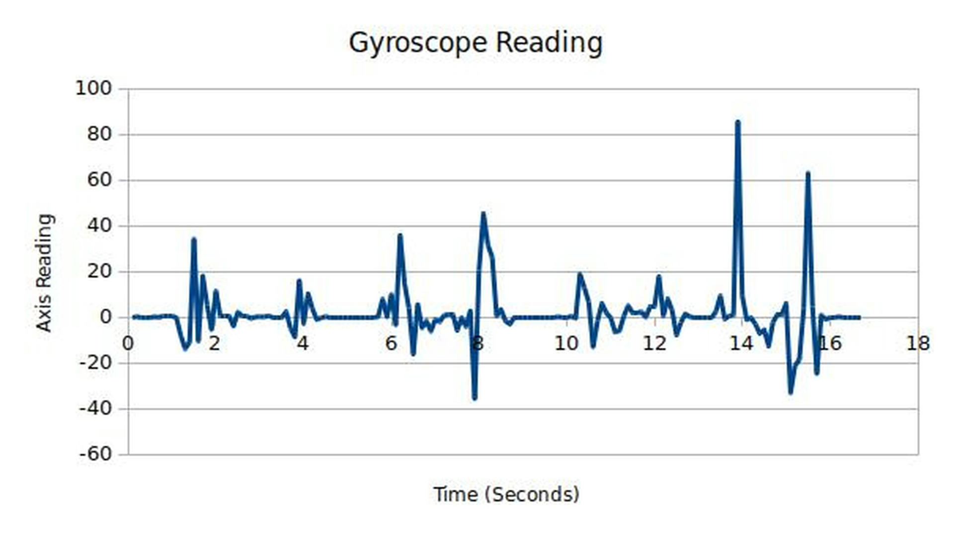
Here's how we can demonstrate this sensor, along with the output:
Accelerometer
Accelerometers measure the lateral acceleration of the sensor (not rotationally). They're how your smartphone knows when it's turned around.
There is a guide to Piezoelectric Accelerometers here that we sound useful. The Engineer Guy also has this great video (along with many more!)
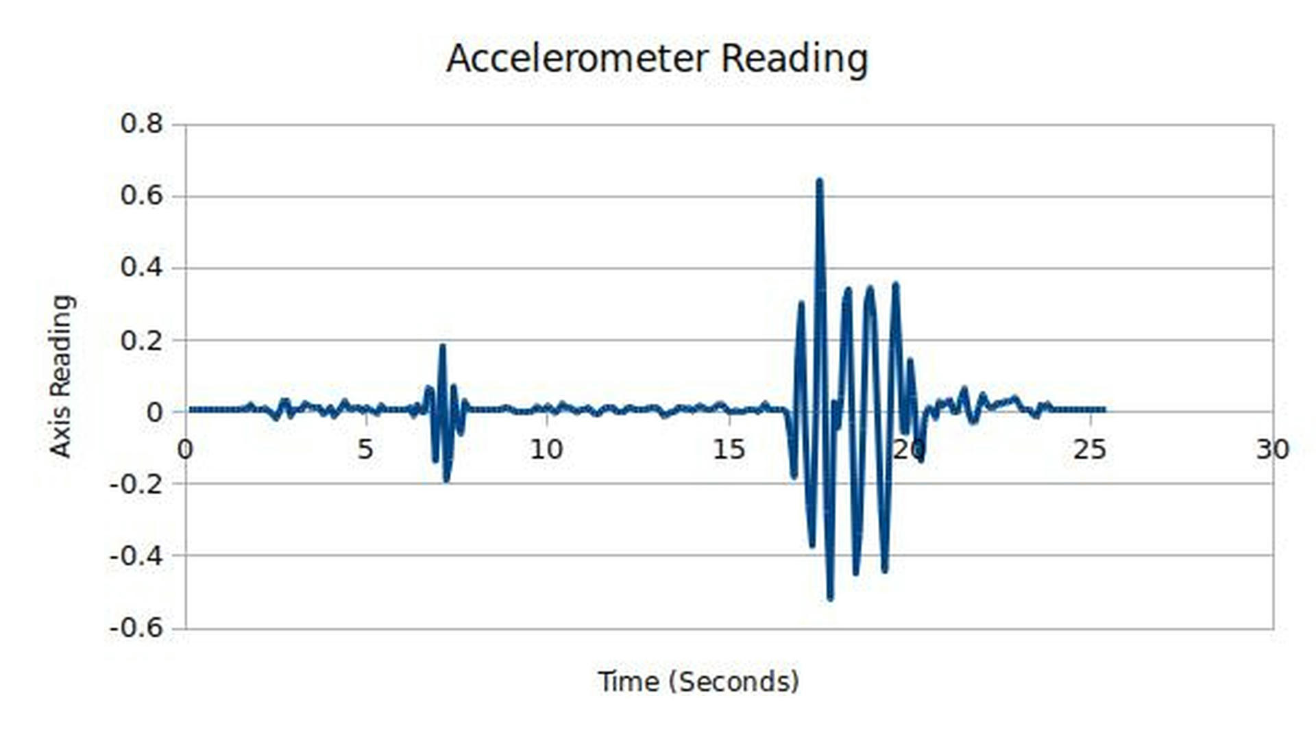
Here's how we can demonstrate this sensor, along with the output:
Some uses of Accelerometers:
- Activity Monitors - Like step counters and skipping counters!
- Vechicle Safety - Accelerometers can detect sudden stops, like vechicle crashes.
- Earthquake Detection - Earthquakes create lots of shifting which an accelerometer can detect and measure.
- Volcanology - Modern accelerometers can be used to detect the flows of magma.
- Computer Inputs - Some new user interface solutions utilize acceleromters to capture input.
Why not velocity? Fun fact: It's impossible to determine if you experiencing a velocity in any direction without a frame of reference. It's much easier to collect acceleration and use mathematics (like something called integration) to determine velocity at a given time. How do we do this?
Imagine that our accelerometer takes measurements every 1 second, and we have 4 readings [1, 2, -2, -1] in centimeters starting from rest. What is the quadcopter doing at the end? How far did it travel? (We'll use basic math here! If you know calculus this is a perfect chance to explain the basics to your cohort.)
- The first second, we have an acceleration of \(1\frac{cm}{s^2}\). We therefore have a velocity of \(1\frac{cm}{s}\). We've travelled 1 cm.
- The second second, we have an acceleration of \(2\frac{cm}{s^2}\). We therefore have a velocity of \(3\frac{cm}{s}\). We've travelled 3 cm.
- The third second, we have an acceleration of \(-2\frac{cm}{s^2}\). We therefore have a velocity of \(1\frac{cm}{s}\). We've travelled 4 cm.
- The fourth second, we have an acceleration of \(-1\frac{cm}{s^2}\). We therefore have a velocity of \(0\frac{cm}{s}\). We've travelled 4 cm.
You can apply the same analysis to gyroscopes.
Pressure Sensor
Pressure Sensors measure the air pressure around the device. The utility of this on a quadcopter may not be obvious at first.
Please, consider the following: The higher you travel in the air, the lower the air pressure becomes.
Therefore if the quadcopter has a reference to the air pressure of where it took off from it is able to understand roughly how high it is relative to that point.
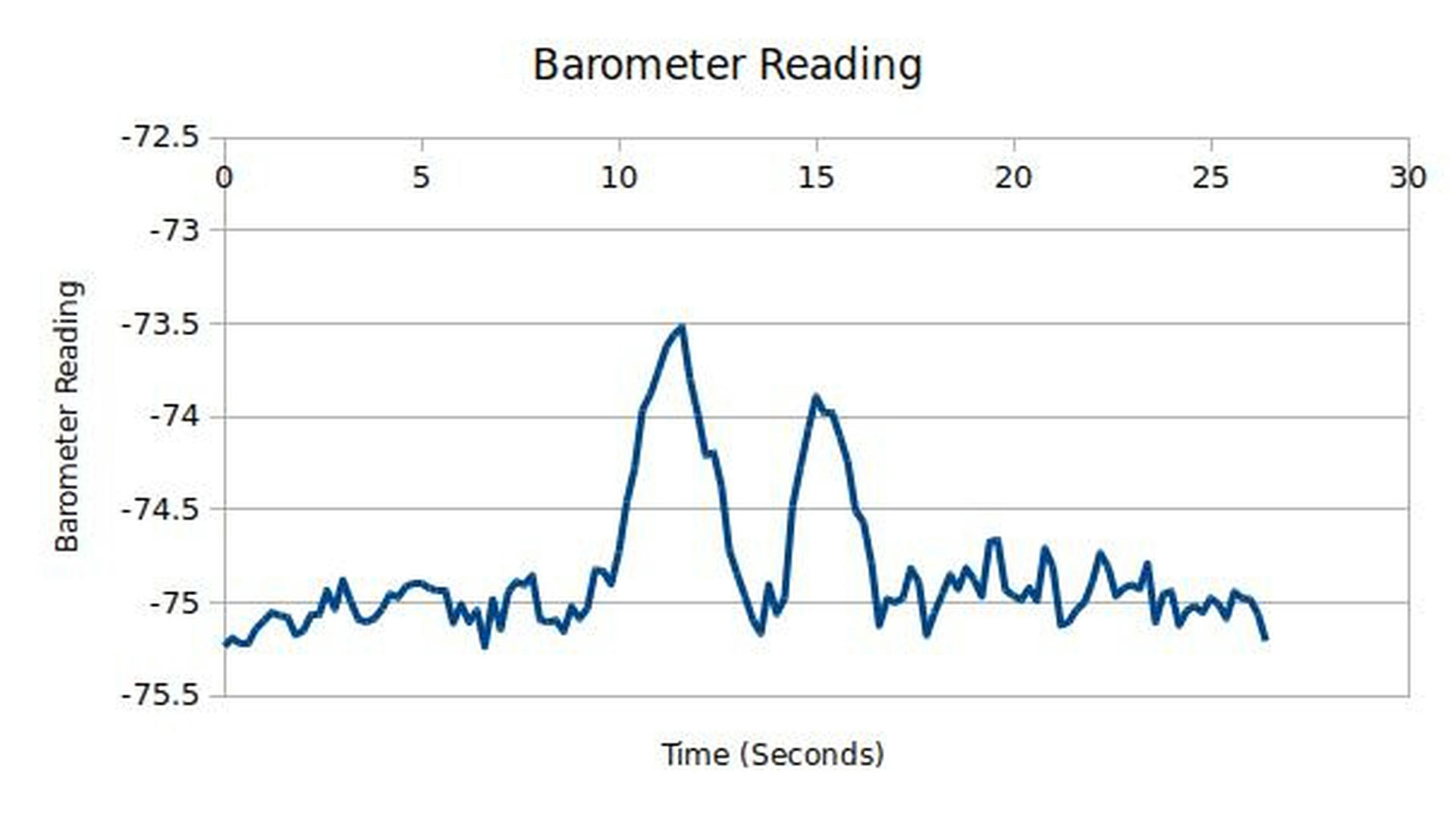
These readings are a bit noisy, sorry.
Sensor Fusion
One interesting technique to improve the sensor readings is to do something called sensor fusion which combines data from disparate sources to help refine measurements. Sensor fusion is a huge benefit to compact or low power systems which often suffer from higher inaccuracies.
One example of sensor fusion which you may have experienced before is stereoscopic vision, when we can use two slightly offset 2D cameras to produce a 3D-looking image.
In our quadcopter the gyroscope, accelerometer, and magnetometer are fused together to improve reduce uncertainty. What exactly does this mean?
When we're measuring a sensor and trying to extract data from it sometimes the input we recieve has variance, like our Barometer readings above. If we combine this data, say with our accelerometer's Z (up-down) axis, we can have a more refined picture of the quadcopter's position, velocity, and acceleration in space instead of just relying on the barometer.
These calculations usually work somewhat similar to this:
\[Result = \frac{(Variance_{Baro}^{-2}*Reading_{Baro}) + (Variance_{Accel Z}^{-2}*Reading_{Accel Z})}{(Variance_{Baro}^{-2} + Variance_{Accel Z}^{-2})}\]
This is called a linear combination of the two measurements, weighted by their variances.
Special thanks to my helper, Laura, for assisting me with capturing stable videography.