Lately we've been playing with Quadcopters a lot, one of the key components of any copter is it's motors! I'll be writing about motors next, but before that I wanted to share some small, short Arduino 'labs' that you can do either on your own or with your cohort!
All of these 'labs' are as inexpensive as we could manage in terms of parts, with the exception of the Arduino.
You're welcome to print, distribute, and modify all of these to meet your needs. You can email me if you'd like the source files. We use Fritzing for breadboard layouts.
On and Off
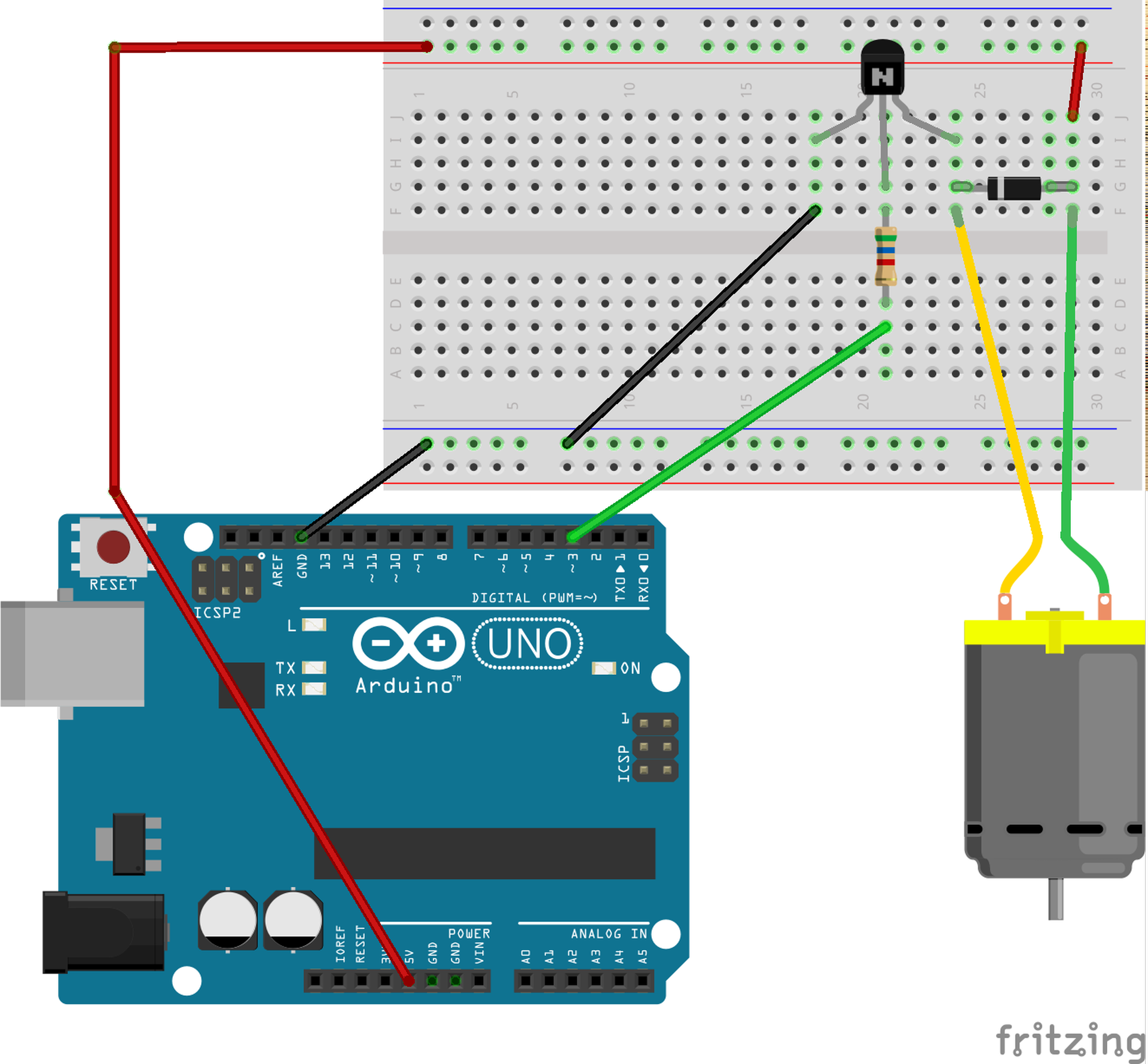
First, let's start with a basic on/off motor. This gives us the chance to understand two particularly important concepts.
Using a transistor as a trigger allows us to safely control larger amounts of voltage with an Arduino pin. If we tried to just use a plain Arduino pin to power the motor we'd risk blowing out the pin as the motor tried to draw many more milliamps than the Arduino can supply through a digital pin.
Using a Diode to handle backcurrent helps prevent any damage that may come from the attached motor is suddenly stopped. This is a neat characteristic in and of itself!
You should see the motor turn on, spin for a pair of seconds, than turn off for two seconds. It will then repeat.
Parts List
- 1x Arduino
- 1x DC Motor (smaller is better)
- 1x Diode
- 1x Resistor (We used 5.6k ohm)
- 1x NPN transistor
- Wires
Breadboard
Code
const int motor = 3;

void setup() {
  pinMode(motor, OUTPUT);
}

void loop() {
  // Motor on.
  digitalWrite(motor, HIGH);

  delay(2000);

  // Motor off.
  digitalWrite(motor, LOW);

  delay(2000);
}
Pulse Width Modulation
If you haven't used Pulse Width Modulation before, it's a way to use certain digital pins on the Arduino to mimic the behaivor of an analog pin, sorta. Essentially PWM makes the pin pulse at specific widths to modulate the signal. This can be used to provide varying amounts of power to something like a motor.
You should see the motor slowly speed up and then back down again.
Supplies & Breadboard
Same as above.
Code
const int motor = 3;
int speed = 0;
int amount = 5;

void setup() {
  pinMode(motor, OUTPUT);
}

void loop() {
  // Use PWM
  analogWrite(motor, speed);

  // Amount will either be + or -
  speed = speed + amount;

  if (speed == 0 || speed == 255) {
    // At a boundary, swap +/- on amount
    amount = -amount;
  }

  delay(30);
}
Reacting to Input
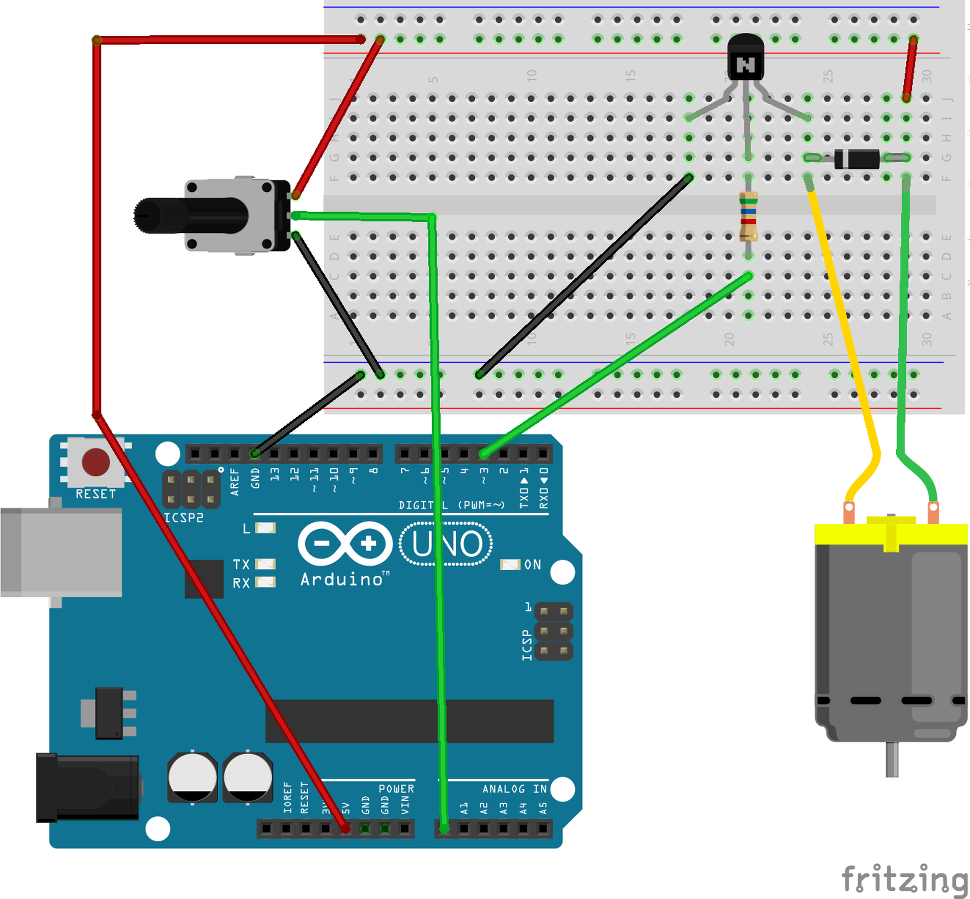
The last few experiments we just used code to change the speed of the motor, however this isn't quite what a quadcopter does. A quadcopter has to take input from sensors and alter the amount of power to the motors accordingly.
You should see the motor's speed change as you turn the potentiometer.
Parts List
Same as above, but add:
- 1x Potentiometer (Or any sensor which offers variable resistance)
Breadboard
Code
const int motor = 3;
const int turnpot = A0;

void setup() {
  pinMode(motor, OUTPUT);
  pinMode(turnpot, INPUT);
}

void loop() {
  int value = analogRead(turnpot);
  analogWrite(motor, value);
  delay(30);
}
I hope you had some fun exploring these basic motor circuits with your Arduino! If you have any other sensor wirings or circuits you'd like to share please just email me and I'll put them here too!