We've already talked a bit about motors in our previous articles, in this article we'll talk more about motors than the quadcopter as a whole.
Motor Basics
We found some great introductory videos which very throughly explain motors and give many great ideas, so instead of replicating their work we chose to share it instead.
Build Your Own
One of the best ways to learn about anything is hands on! Why not try to make a motor yourself, or with your cohort?
The below video explains how you can build a simple motor out of some basic supplies. This project is more suitable for younger or less technically inclined humans. Note that the motors used in a Quadcopter are slightly more sophisticated.
Tinker or Make a Demo
The below video has a fantastic, in-depth explaination of how motors work and includes a number of setups which can help you understand the mechanics and motion of a motor.
If you have any old drills or other motored devices hanging around (or found at the thrift store) you can transform it into a number of great demos.
Getting your hands on something is unquestionably the best way to learn, having demos and experiments is a fantastic way to enhance your lessons or self-study.
Measuring the Motor
In order to get some firm measurements about the motor, we built an apparatus to hold it and attached wires to it.
Since we didn't want to damage the motor we were careful and used very small wire looped into the connector. Then we used tape to keep the copper wires seperate. The wires touching would cause a short circuit and be very bad (resulting in smoke and an angry motor.)
After that was complete we used an adjustable soldering stand to hold the motor up in the path of a photogate sensor. The idea was to use the propellor to break the photogate's beam and use the number of breaks to determine the rotations per minute (RPM) of the propellor at various speeds.
With the motor held safely, the photogate in place, and the power supply wired in to provide power to the motor, we attached our photogate to a measurement device to start our experiment.
Failure. It turns out that the software was unable to effectively measure the propellor at higher speeds. The quadcopters motors are rated up to 14,000 RPM and it's understandable that standard equiptment might struggle with this.
This threw us for a bit of a loop but we figured out a better, simpler method. We decided to utilize a strobe light to "stop" the motor.
How can a strobe light be used to measure RPM?
First the strobe light pulses its light at a constant, uniform rate, and the motor is turning at a (mostly) constant, uniform rate. Because of this, if the strobe light pulses at some amount of pulses per minute ($$ PPM $$) which is equal to the motors rotations per minute ($$ RPM $$) then each pulse of light will shine on approximately the same image of the motor. This image is what we see observing it.
$$ PPM = RPM $$
You can see how it looks in this below video, apologies for the video quality and loud sound, strobes are noisy and cameras don't image the way our eyes do.
This is a very fun and curious experiment to try on your own or with your cohort however strobe lights can be hard to source.
Measurements
Using a pair of multimeters and an adjustable power supply we could take measurements of the motor at various power settings.
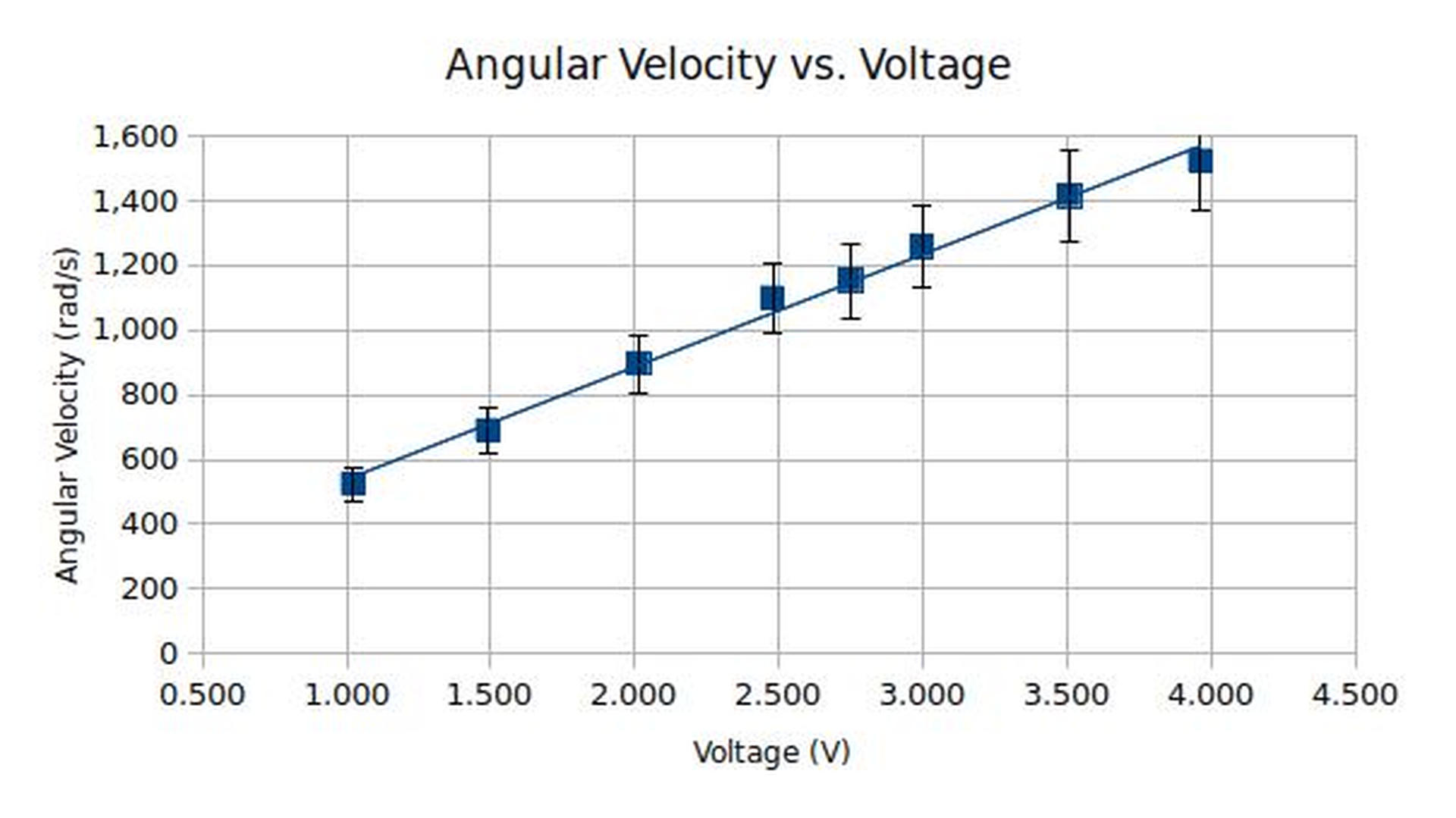
First, let's take a look at the relationship between voltage and the rotations per minute (RPM) of the propeller. Voltage is the difference in potential between the hot and ground wires.
If you picture yourself as an electron walking along a road (the wire), you can picture voltage as how steep the hill is.
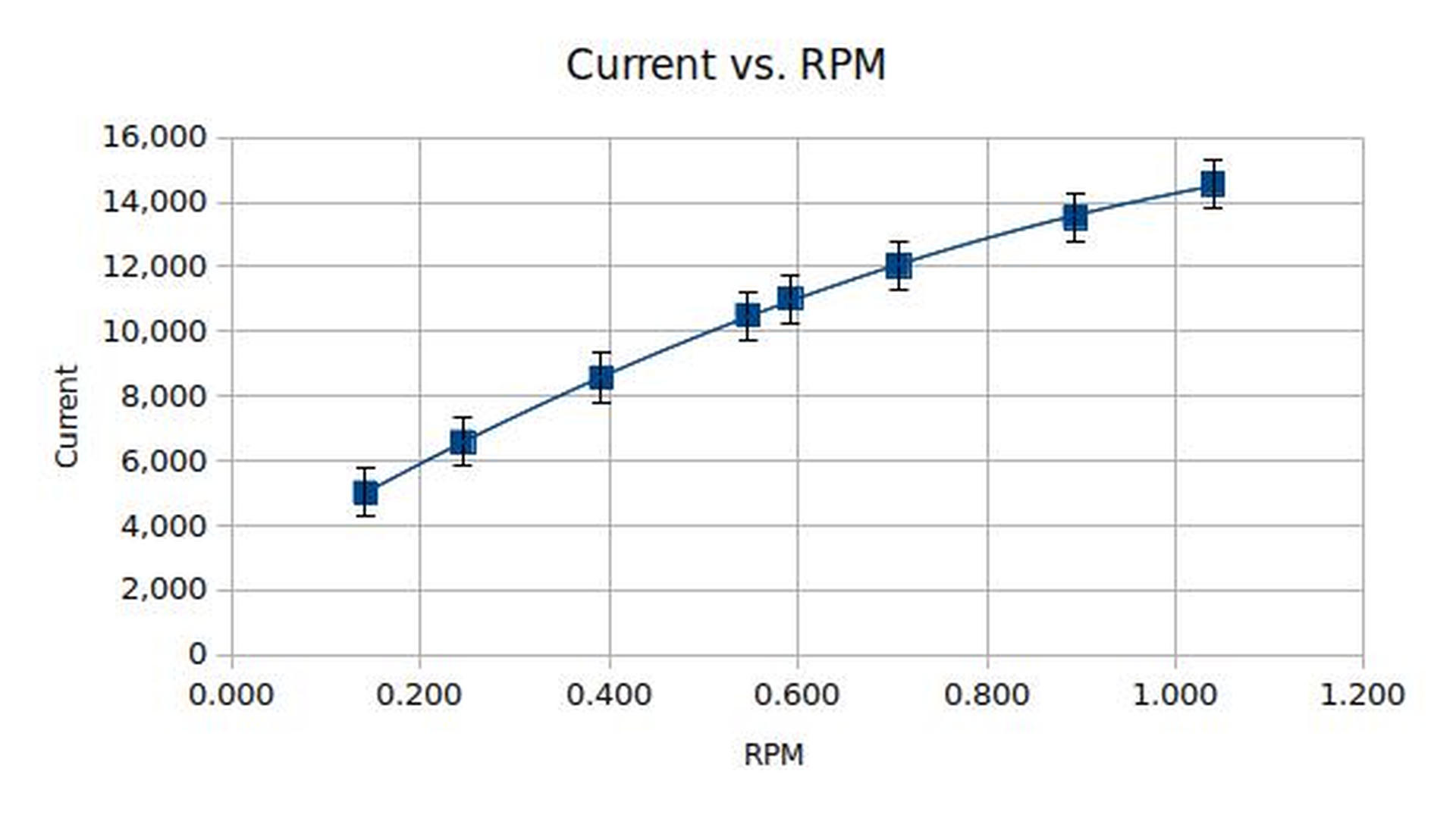
The relationship that current and the rotations per minute have is also very much a straight line.
If you picture yourself as an electron current is how hard you're pushing against something.
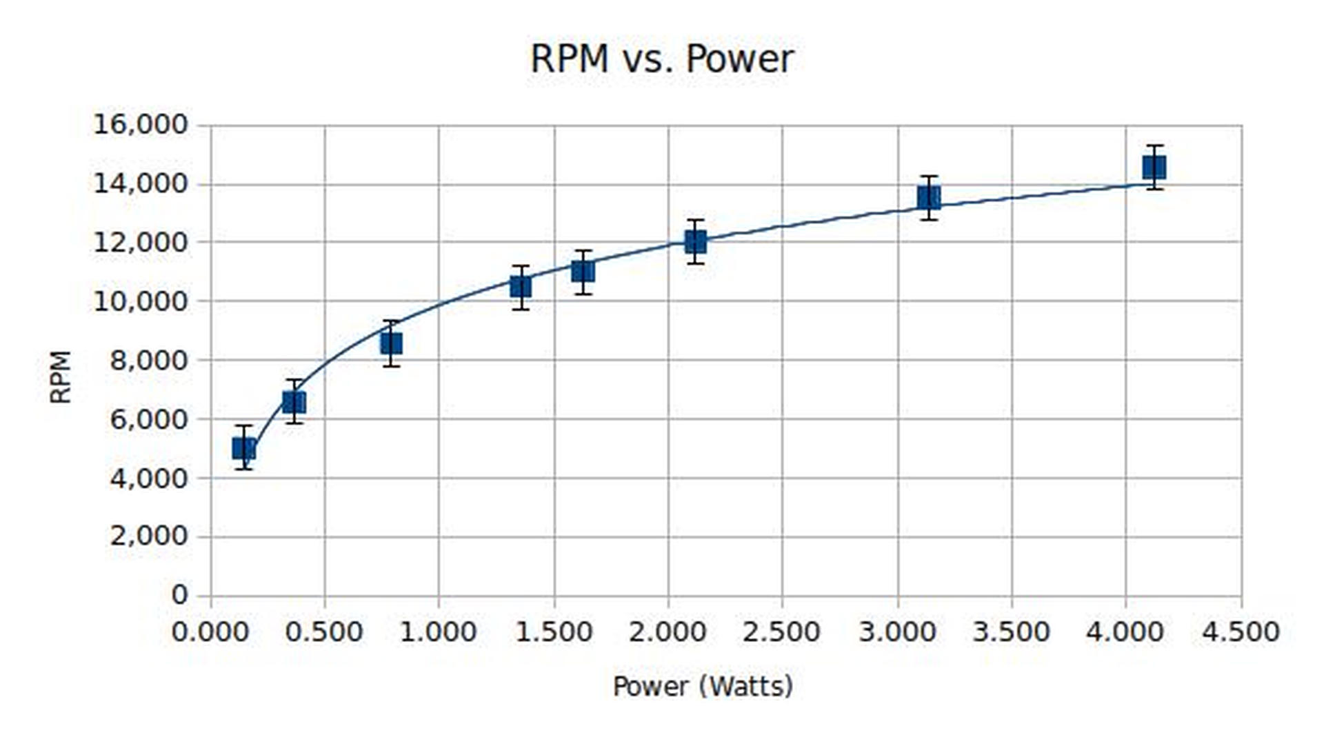
The power of the motor is equals to the voltage times the current. You can see that this relationship is a nice, smooth curve. It's interesting to note that there are diminishing returns the more power you put in.
$$ voltage * current = power $$
The angular velocity is the speed at which the blade of the propeller is rotating around the motor's axis. This relationship is straight, just like the voltage vs RPM graph.
$$ velocity_{angular} = RPM * \frac{2\pi}{60 seconds} $$
Motors in Action
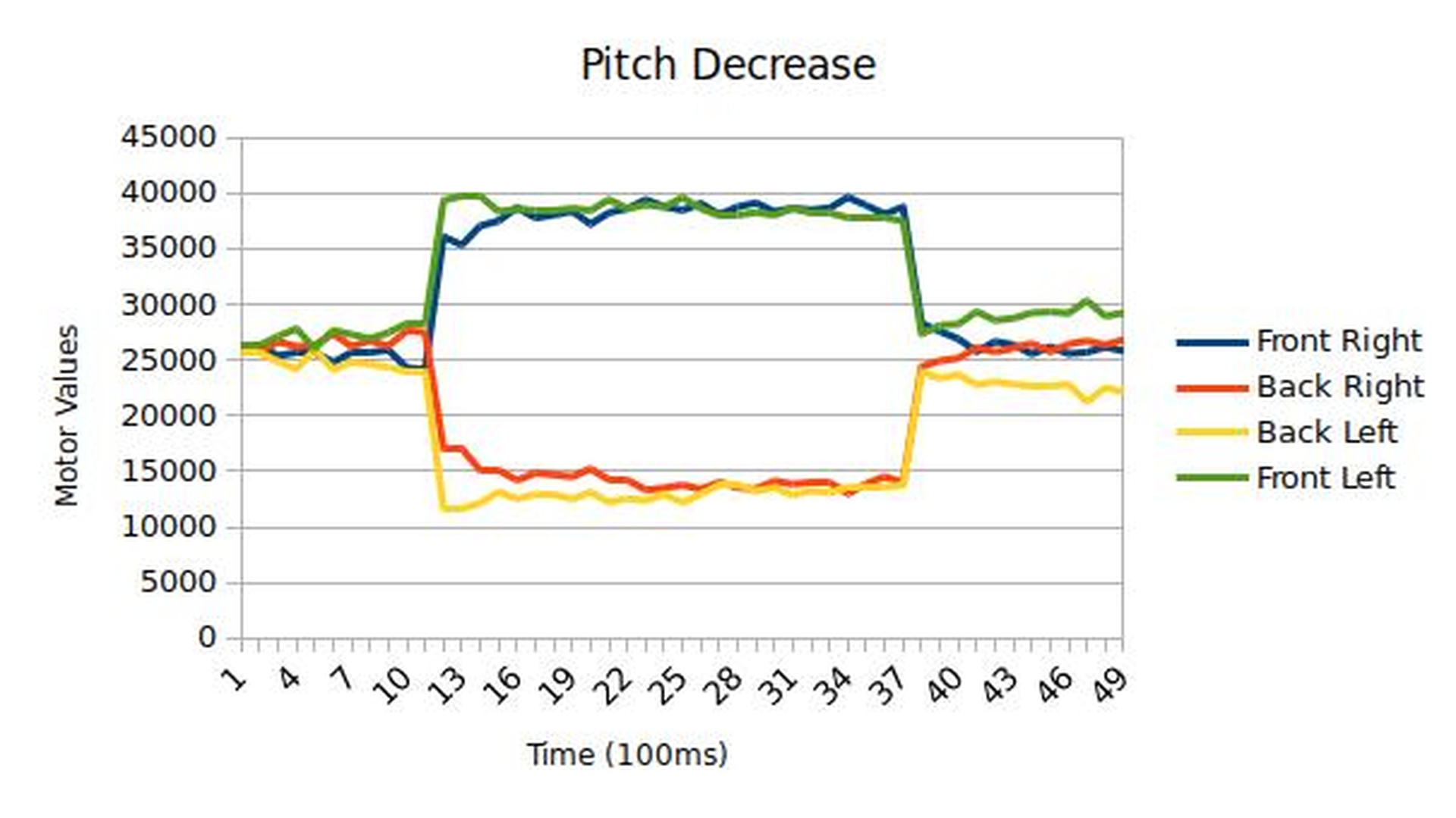
In the following graphs we captured data from the quadcopter using the Crazyflie client's logging functionalities. A motor value of 0 indicates that no power was sent to the motor, while a higher number means more power was sent. (We asked the Bitcraze folks what these values represented here.)
In order to capture this data we held the quadcopter (mostly) in place and fully triggered given inputs. The wobble you see in the motor plots is due to variances in the outputs of the stablization algorithms as they react on sensor input.
Pitch
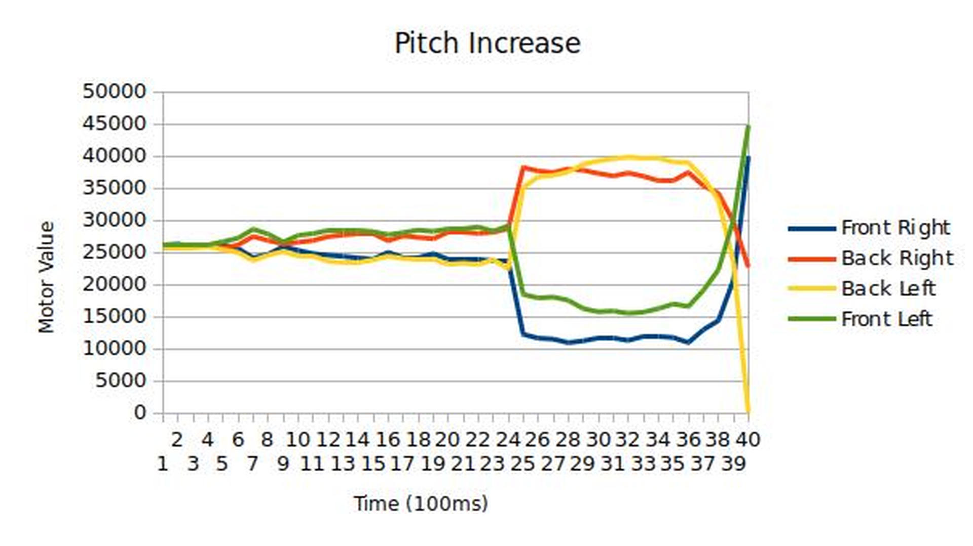
In these you can see the very clear demonstration of the front motor and rear motors raising or lowering depending on the input.
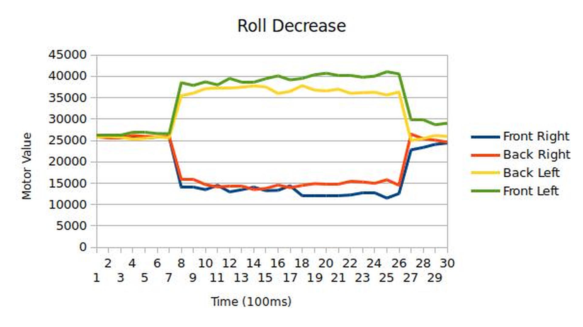
Roll
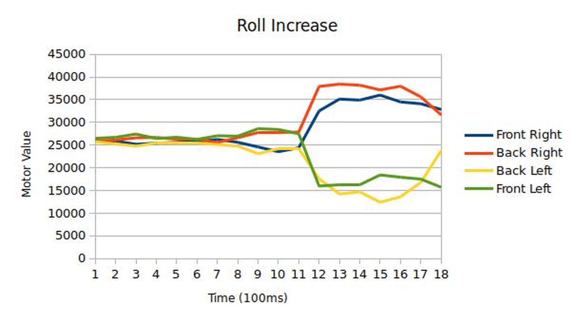
In these you can observe the left and right motors changing accordingly.
Yaw
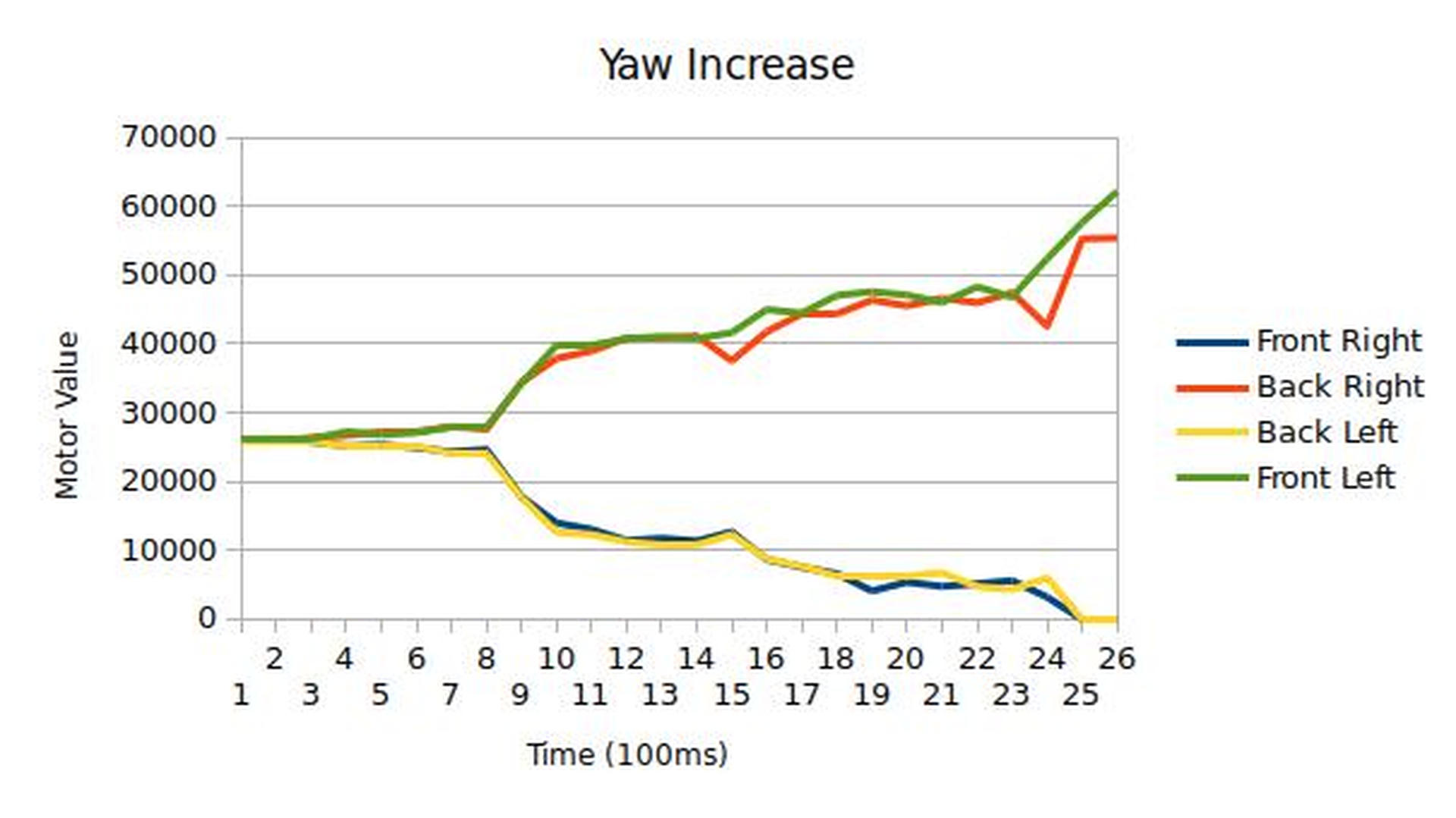
Finally, in these you can see the diagonal motors changing as we've previously discussed.